
Data modeling is the process of creating a visual representation of an organization’s data and the relationships between different pieces of that data. For example, imagine a retail business that tracks sales, customers, and inventory – data modeling would illustrate how these elements connect, such as which customers bought which products and how it affects inventory levels. It’s a way to structure information clearly, making it easier to manage, analyze, and use across systems.
This task is typically carried out by data architects, database administrators, and business analysts, each contributing their expertise to ensure the models meet both technical and business needs. The process is broken down into three main steps and types:
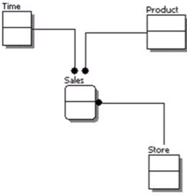
1. Conceptual Data Modeling: The big picture, focused on what needs to be captured without technical details.
2. Logical Data Modeling: Adds structure and business rules to the conceptual design.
3. Physical Data Modeling: Converts the logical design into a database schema with storage and performance considerations.
Contents
Conceptual Data Modeling
What It Is
Conceptual modeling is about defining the general framework for data without diving into the technical details. For example, a healthcare organization might use conceptual modeling to outline the relationship between patients, doctors, and appointments. This stage identifies that patients schedule appointments with doctors but doesn’t yet specify technical details like database fields or storage methods.
It focuses on entities (e.g., Customer, Product) and the general relationships between them, so it is highly abstract and easily understandable also for non-technical stakeholders.
Example
Imagine a company wants to track orders. At this stage, you might identify the following entities:
- Customer
- Product
- Order
The relationships between them (e.g., “a customer places an order”) are noted but not deeply explored yet.
Logical Data Modeling
Logical data modeling bridges the gap between the broad conceptual model and the detailed physical implementation. It focuses on business rules, concepts, and the relationships between data entities. Attributes and key attributes are present now, so the Primary Key – Foreign Key relationship is defined.
It is typically created using Entity-Relationship Diagrams (ERDs). By defining entities, attributes, and relationships, logical modeling ensures that technical teams have a clear, actionable structure to work from while still aligning with business requirements. This model sets the stage for creating a database that accurately represents the organization’s data needs. It answers the question: What data do we need, and how does it all connect?
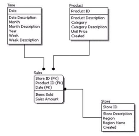
Key Elements
- Entities: Objects or concepts like Customer or Product.
- Attributes: Characteristics of an entity such as “Customer Name” or “Product Price.”
- Relationships: How entities are connected, such as “a customer places orders.”
Cardinality and Relationships
Logical models define how entities interact. For example:
- One-to-One (1:1): Each instance of Entity A relates to exactly one instance of Entity B (e.g., a person has one passport).
- One-to-Many (1:N): Each instance of Entity A relates to multiple instances of Entity B (e.g., a customer places multiple orders).
- Many-to-Many (N:N): Each instance of Entity A relates to many instances of Entity B and vice versa (e.g., students enroll in multiple courses, and courses have multiple students).
Steps to Build a Logical Model
- Identify all entities and their relationships.
- Define attributes for each entity.
- Normalize the data to reduce redundancy.
- Use Entity-Relationship Diagrams (ERDs) to visualize the model.
How ERDs Work
An Entity-Relationship Diagram (ERD) is a visual representation of the structure of a database. It illustrates the entities (tables), attributes (columns), and relationships (links between tables) within the system. How to design it?
- Entities: Shown as rectangles.
- Attributes: Listed inside the entity rectangles.
- Relationships: Represented with diamonds or labeled lines (show how entities are connected).
- Keys: Primary Keys (underlined in the attribute list) and Foreign Keys (marked as FK).
For the Cardinality “Crow’s Foot Notation” it’s used and preferred in modern ERDs:
|—|: One.
|—<: Many.
O—: Optional.
Physical Data Modeling
Once the logical model is finalized, it’s time to implement it in a database. Physical modeling focuses on how data is stored and optimized for performance, adding technical details such as data types, indexing, and storage.
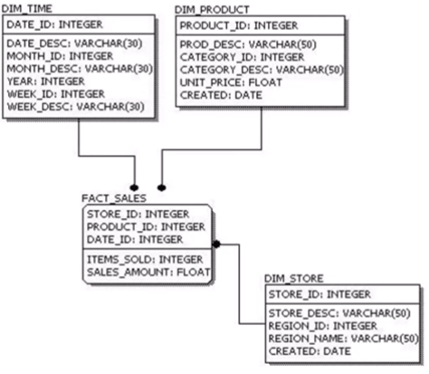
Key Components
- Tables: Represent entities.
- Columns: Represent attributes.
- Indexes: Help optimize query performance.
Constraints
- Primary Key (PK): Uniquely identifies each row in a table.
- Foreign Key (FK): Links related tables.
- Unique Key: Ensures no duplicate values in specific columns.
- Check Constraints: Enforce rules (e.g., “age must be greater than 18”).
Steps in Physical Modeling
- Map logical entities to database tables.
- Define columns and their data types.
- Add constraints like PKs and FKs.
- Create indexes for performance.
- Implement and test the schema in the database.
Technical Considerations
- Surrogate Keys: Artificial unique identifiers, IDs (e.g., CustomerID).
- Natural Keys: Derived from actual business data (e.g., Social Security Number).
- Common Data Types:
- INT for whole numbers.
- FLOAT for fractional numbers.
- VARCHAR(n), CHAR(n), TEXT for variable-length text.
- DATE, DATETIME, TIMESTAMP for dates.
- BLOB for binary files.
Connecting Logical and Physical Models
A logical model lays the foundation by defining the structure and relationships of the data, while a physical model translates this into an actual database that functions efficiently. Here’s how they are connected:
- Entities become Tables: Each entity in the logical model translates into a table in the physical model.
- Attributes become Columns: Attributes of an entity become the columns of the corresponding table.
- Primary Keys and Foreign Keys define relationships: PKs are defined in the physical table for each entity, FKs enforce relationships between tables.
Logical models don’t account indexes (aggregate frequently queried columns) for performance. In physical models, you introduce:
- Clustered Indexes: Organizes rows in a specific order, making range-based queries faster.
- Non-Clustered Indexes: Pointers, allowing the database to quickly locate rows without scanning the entire table.
Conclusion
Data modeling is the backbone of creating an effective and reliable database. It starts with conceptualizing how data will flow within a system and ends with implementing the technical details that make it functional. By following the steps of data modeling, businesses can ensure that their data is not only well-structured but also accessible and practical for everyday use. With the right techniques, companies can transform raw data into actionable insights, streamlining operations and supporting better decision-making.
FAQs
1. What is the purpose of data modeling?
Data modeling helps organize and manage data effectively, ensuring consistency and usability across systems.
2. How do logical and physical models differ?
Logical models focus on defining relationships and rules, while physical models implement these designs with database-specific details.
3. Why are ERDs important?
Entity-Relationship Diagrams visually clarify the structure of a database, making it easier to design and communicate.
4. What is normalization?
Normalization minimizes redundancy and organizes data efficiently, ensuring consistency and accuracy. A full article on normalization techniques and their practical applications will be coming soon to dive deeper into this topic.
5. What are surrogate keys?
Surrogate keys are unique identifiers created artificially, useful when natural keys (like Social Security Numbers) are unavailable or impractical.